visual FIRE PREVENTION THERMOLABELS (vFPT)
vFPT helps maintenance personnel understand the condition of the equipment, not only at the time of inspection, but can also see if the equipment has reached a certain temperature in the past. Unlike using a thermal imager, vFPT provides a clear picture of what has happened since the last check. These labels are extremely easy to install for any configuration of electrical equipment.
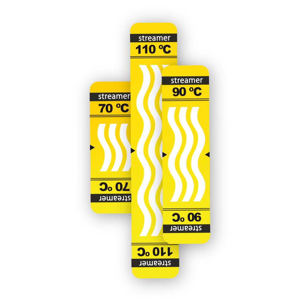
1-TEMPERATURE vFPT
The principle of operation is simple: at the activation temperature (70, 90 or 110 °C ) the white strips irreversibly change color to black.
Single-temperature vFPT thermal indicators detect overheating above the set maximum allowable temperature.
•vFPT provides information on overheating occurred between 2 checks.
•More effective way of tracking contact connections temperature than traditional visual inspection and infrared thermography (IRT).
•Long strips allow to get 360° angle of observation.
•Specially designed for installation on electrical equipment
•10 years of validity period.
•Single-temperature vFPT allows to determine the maximum exceeded temperature during operation of electrical equipment.
•Control hard-to-reach or inaccessible elements for the thermal imager (MV switchgear, explosion-proof electrical equipment)

|
Activation temperature |
Item name | Conductor cross-section,mm² | Reference |
|
70 °C |
vFPT 70S | up to 10 | FP.VT.070A.Y1.WW |
|
70 °C |
vFPT 70M |
10-35 |
FP.VT.070B.Y1.WW |
|
70 °C |
vFPT 70L |
35-120 | FP.VT.070C.Y1.WW |
|
90 °C |
vFPT 90S | up to 10 | FP.VT.090A.Y1.WW |
|
90 °С |
vFPT 90M |
10-35 |
FP.VT.090B.Y2.WW |
|
90 °С |
vFPT 90L |
35-120 |
FP.VT.090C.Y2.WW |
|
110 °С |
vFPT 110S |
up to 10 |
FP.VT.110A.Y1.WW |
|
110 °C |
vFPT 110M | 10-35 | FP.VT.110B.Y1.WW |
|
110 °C |
vFPT 110L |
35-120 | FP.VT.110C.Y2.WW |
|
Other temperature vFPT can be created on request with a minimum order quantity |
|||
|
|
S |
M |
L |
|
|
Length, mm |
40 |
50 |
75 |
|
|
Width, mm |
15 |
15 |
15 |
|
4-TEMPERATURES vFPT
Four vFPT temperature indicators allow to determine the maximum temperature to which overheating occurred and detect differences in heating of identical units (phases, motors, mechanical devices), allowing to understand the exact reason of the overheating.

•Detect defects at early stages.
•4-temperatures vFPT allows you to understand not only if the contact has reached highest permissible temperature but also to see how defect evolves and understand the reasons of overheating
• Reduce the risk of fires in electrical installations.
•10 years of validity period.
•Control hard-to-reach or inaccessible elements for the thermal imager (MV switchgear, explosion-proof electrical equipment).
| Length, mm | 50 | |||||||
| Width, mm | 20 | |||||||
|
Conductor cross-selection, mm2
|
10-120 | |||||||
| Standart range vFPT |
FP.VT.612C.Y1.WW — 60-80-100-120 °C FP.VT.811C.Y1.WW — 80-90-100-110 °C Other set of temperatures can be created on request with a minimum order quantity |
|||||||
| Possible temperature range, °C | 50 | 60 | 70 | 80 | 90 | 100 | 110 | 120 |