Fault indicators
When reliable and fast indication of the failure section is needed after a short circuit, the fault detectors are a must-have. Fault circuit indicator is used to detect short circuit failures or phase-to-earth faults in electric power distribution networks. By reporting each incident via visual or remote signal, the fault indicators reduce substantially the time and costs needed to find out the source of a fault.
The products
| Pole Mounted Pathfinder | Portable MK |
|
|
|
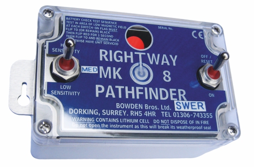
| Mk8 |
MK9B |
MK10 | |
|
Portable / permanent installed |
Portable | Portable | Portable |
|
Position of installation |
Pole – on eye level | Pole – on eye level | Pole – on eye level |
|
Operating line voltage |
High Sensitivity 14A. Low Sensitivity 70A |
Sensitive earth fault 4A. Normal 15A |
High Sensitivity 14A. Low Sensitivity 70A |
|
Communication |
– |
– |
GSM/GPRS |
|
Fault indication |
Red flag | Red flag | Red flag+COM |
|
Fault phase indication |
– |
– |
– |
|
Fault direction indication |
– |
– |
– |
|
Difference transient / permanent fault |
– |
– |
– |
|
Configuration |
Manual |
Manual |
Manual or COM |
|
Live line installation |
Yes |
Yes |
Yes |
| Connect to SCADA |
– |
– |
– |
| Option | 3 pcs carry-on case | 3 pcs carry-on case |
3 pcs carry-on case Software |
|
|
P360 A | P360 A ROSCO | P360 AC GSM | P360 AC GPRS |
|
Portable / permanent installed |
Permanent |
Permanent |
Permanent |
Permanent |
| Place of installation | Pole – 3m below conductors | Pole – 3m below conductors | Pole – 3m below conductors | Pole – 3m below conductors |
| Operating line voltage | 6kV - 66kV | 6kV - 66kV | 6kV - 66kV | 6kV - 66kV |
| Min fault current | 12A | 12A | 12A | 12A |
| Fault indication | LED | LED | LED | LED |
| Fault sending |
— |
Wire output | SMS sending | Data sending via GPRS |
| Fault phase indication |
— |
— |
— |
— |
| Fault direction indication |
— |
— |
— |
— |
| Difference transient / permanent fault |
Yes |
Yes |
Yes |
Yes |
| Connect to SCADA |
— |
Yes |
— |
Yes |
How does fault indicator work?
- The fault indicator should be placed on key locations on the line like at the beginning of branches
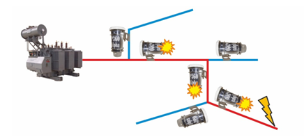
- In case of a fault, the short circuit loop will go from the fault source to the supplying substation
- Each fault indicator located on that path will detect and indicate the fault. The devices will have a visual indication and can send the information via SMS/GPRS
- It becomes then easy to find the fault source by just following the path indicated by the fault indicators.

Main features of the fault indicators
- high indication visibility, thanks to high-brightness LED;
- failure fault information transmitted straight to the control station, using the GSM-connection or GPRS;
- auto setting feature: the fault indicator detects the normal electromagnetic field and set itself compare to it. If the load is changing, the fault indicator adapts to it
Pole mounted fault indicator principle
 |
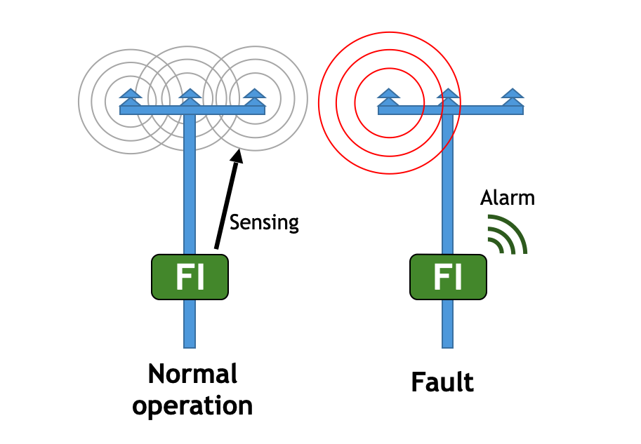
When it is needed to equip the line with fault indicators, the pole mounted range from Streamer Electric AG is a cost effective solution. The conductors’ electromagnetic field is sensed by the device. When the field is balanced, the fault indicator considers it as a normal situation thanks to the auto setting feature. During a fault the electromagnetic field will quickly shift and become unbalanced. This change is detected by the fault indicator which will go in alarm mode. |


